Excellent software and practical tutorials


1. Quick Start
If you want to do your work well, you must first sharpen your tools! WireGuard The general process is as follows:
Preparation
View the current kernel version
uname -r #4.18.0-348.2.1.el8_5.x86_64 uname -a #Linux mir4 4.18.0-348.2.1.el8_5.x86_64 #1 SMP Tue Nov 16 14:42:35 UTC 2021 x86_64 x86_64 x86_64 GNU/Linux cat /etc/redhat-release #CentOS Linux release 8.5.2111
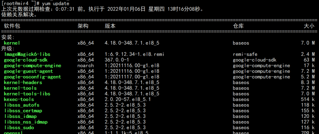
Upgrade the system kernel
dnf -y update
Install EPEL repository on CentOS 8.x
EPEL stands for “Extra Packages for Enterprise Linux”, which is a free and open source repository of additional packages available for CentOS and RHEL servers. As the name suggests, the EPEL repository provides additional packages that are not available in the default package repositories of CentOS 8 and RHEL 8.
epel official website:https://fedoraproject.org/wiki/EPEL/zh-cn
dnf search epel #epel-next-release.noarch : Extra Packages for Enterprise Linux Next repository configuration #epel-release.noarch : Extra Packages for Enterprise Linux repository configuration #Check the epel-release version in the system software repository dnf info epel-release #Install the epel source from the system software repository dnf install epel-release #Install the epel source from the website via the URL dnf install https://dl.fedoraproject.org/pub/epel/epel-release-latest-8.noarch.rpm #Enable the PowerTools repository because EPEL packages may depend on packages in these repositories dnf config-manager --set-enabled powertools #After successful installation, test the number of packages in the repository sudo dnf --disablerepo="*" --enablerepo="epel" list available | wc -l
Install ELRepo repository on CentOS 8.x
The ELRepo repository is a community-based enterprise Linux repository that provides support for RedHat Enterprise (RHEL) and other RHEL-based Linux distributions (CentOS, Scientific, Fedora, etc.).
ELRepo focuses on hardware-related software packages, including file system drivers, graphics drivers, network drivers, sound card drivers, and camera drivers.
#Import the public key of the ELRepo repositoryrpm --import https://www.elrepo.org/RPM-GPG-KEY-elrepo.org #Install the yum source of the ELRepo repositorydnf install https://www.elrepo.org/elrepo-release-8.el8.elrepo.noarch.rpm #Check the kernel versiondnf --disablerepo="*" --enablerepo="elrepo-kernel" list available
The eple and ELRepo repositories need to be installed on the server before wireguard can be installed.
# After the software source is installed, clear the cache dnf clean all # recreate the cache of the repository yum makecache reboot
Install
Official installation reference:https://www.wireguard.com/install/
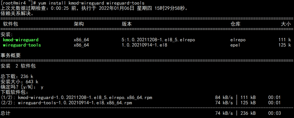
The following are installation methods for several operating systems, including Centos8, Centos7, Ubuntu, and MacOS.
#CentOS8 dnf install elrepo-release epel-release dnf config-manager --set-enabled powertools dnf copr enable jdoss/wireguard dnf install wireguard-dkms wireguard-tools #CentOS7 yum install epel-release https://www.elrepo.org/elrepo-release-7.el7.elrepo.noarch.rpm yum install yum-plugin-elrepo yum install kmod-wireguard wireguard-tools #If you are using a non-standard kernel, you need to install the DKMS package yum install https://dl.fedoraproject.org/pub/epel/epel-release-latest-7.noarch.rpm curl -o /etc/yum.repos.d/jdoss-wireguard-epel-7.repo https://copr.fedorainfracloud.org/coprs/jdoss/wireguard/repo/epel-7/jdoss-wireguard-epel-7.repo yum install wireguard-dkms wireguard-tools #Ubuntu≥18.04 apt install wireguard #Ubuntu≤16.04 add-apt-repository ppa:wireguard/wireguard apt-get update apt-get install wireguard #MacOS brew install wireguard-tools
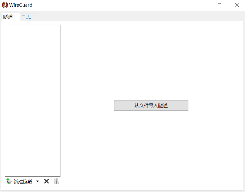
Windows client download address:
- https://download.wireguard.com/windows-client/wireguard-amd64-0.1.1.msi
- https://download.wireguard.com/windows-client/wireguard-installer.exe
Android and iOS can download the relevant client through the app store:
https://www.wireguard.com/install/#installation


Enable IP address forwarding on the relay server:
echo "net.ipv4.ip_forward = 1" >> /etc/sysctl.conf
echo "net.ipv4.conf.all.proxy_arp = 1" >> /etc/sysctl.conf
sysctl -p /etc/sysctl.conf
Add iptables rules to allow NAT translation on this machine:
iptables -A INPUT -m conntrack --ctstate RELATED,ESTABLISHED -j ACCEPT iptables -A FORWARD -m conntrack --ctstate RELATED,ESTABLISHED -j ACCEPT iptables -A FORWARD -i wg0 -o wg0 -m conntrack --ctstate NEW -j ACCEPT iptables -t nat -A POSTROUTING -s 192.0.2.0/24 -o eth0 -j MASQUERADE
You need to change eth0 to the name of the network card interface you actually use.
Writing configuration files
The configuration file can be placed in any path, but must be referenced by an absolute path. The default path is /etc/wireguard/wg0.conf.
# create a configuration file vi /etc/wireguard/wg0.conf
Generate Keys
Generate a private key
wg genkey > example.key
Generate Public Key
wg pubkey < example.key > example.key.pub
Start and stop
$ wg-quick up /full/path/to/wg0.conf
$ wg-quick down /full/path/to/wg0.conf
# Start/Stop VPN network interface
$ ip link set wg0 up
$ ip link set wg0 down
# Register/Unregister VPN Network Interface
$ ip link add dev wg0 type wireguard
$ ip link delete dev wg0
# Register/Deregister Local VPN Address
$ ip address add dev wg0 192.0.2.3/32
$ ip address delete dev wg0 192.0.2.3/32
# Add/Delete VPN Routes
$ ip route add 192.0.2.3/32 dev wg0
$ ip route delete 192.0.2.3/32 dev wg0
View information
interface:
# View system VPN interface information
$ ip link show wg0
# View VPN interface details
$ wg show all
$ wg show wg0
address:
# View VPN interface address
$ ip address show wg0
routing
# View system routing table
$ ip route show table main
$ ip route show table local
# Get the route to a specific IP
$ ip route get 192.0.2.3
One-click installation
For one-click installation, please refer to this project: WireGuard installer[3]
2. Configuration details
WireGuard uses INI[4] The configuration file format is /etc/wireguard/wg0.conf. The configuration file can be placed in any path, but must be referenced by an absolute path. The default path is /etc/wireguard/wg0.conf.
The configuration file must be named ${name of the WireGuard interface}.conf. Usually the WireGuard interface name is prefixed with wg and numbered starting from 0, but you can use other names as long as they match the regular expression ^[a-zA-Z0-9_=+.-]{1,15}$.
You can choose to manually configure the VPN using the wg command, but it is generally recommended to use wg-quick, which provides a more powerful and user-friendly configuration experience and can manage configuration through configuration files.
The following is an example configuration file:
[Interface]
# Name = node1.example.tld
Address = 192.0.2.3/32
ListenPort = 51820
PrivateKey = localPrivateKeyAbcAbcAbc=
DNS = 1.1.1.1,8.8.8.8
Table = 12345
MTU = 1500
PreUp = /bin/example arg1 arg2 %i
PostUp = /bin/example arg1 arg2 %i
PreDown = /bin/example arg1 arg2 %i
PostDown = /bin/example arg1 arg2 %i
[Peer]
# Name = node2-node.example.tld
AllowedIPs = 192.0.2.1/24
Endpoint = node1.example.tld:51820
PublicKey = remotePublicKeyAbcAbcAbc=
PersistentKeepalive = 25
[Interface]
This section defines the local VPN configuration. For example:
The local node is a client that only routes its own traffic and exposes only one IP.
[Interface]
# Name = phone.example-vpn.dev
Address = 192.0.2.5/32
PrivateKey =The local node is a relay server that forwards traffic to other peers and exposes the routing of the entire VPN subnet.
[Interface]
# Name = public-server1.example-vpn.tld
Address = 192.0.2.1/24
ListenPort = 51820
PrivateKey =
DNS = 1.1.1.1
① # Name
This is a standard comment in INI syntax used to show which node this portion of the configuration belongs to. This portion of the configuration is completely ignored by WireGuard and has no effect on the behavior of the VPN.
② Address
Defines which address range the local node should route to. If it's a regular client, set this to the single IP of the node itself (specified using CIDR, e.g. 192.0.2.3/32); if it's a relay server, set this to a routable subnet range.
For example:
Regular client, only routes its own traffic: Address = 192.0.2.3/32 Relay server, which can forward traffic to other peer nodes (peers): Address = 192.0.2.1/24 You can also specify multiple subnets or IPv6 subnets: Address = 192.0.2.1/24,2001:DB8::/64
③ ListenPort
When the local node is a relay server, you need to specify the port to listen for incoming VPN connections through this parameter. The default port number is 51820. Regular clients do not need this option.
④ PrivateKey
The private key of the local node must be set for all nodes (including relay servers). It cannot be shared with other servers.
The private key can be generated by command wg genkey > example.key.
⑤ DNS
Announces DNS servers to clients via DHCP. Clients will use the DNS servers specified here to handle DNS requests in the VPN subnet, but this option can also be overridden in the system. For example:
If not configured, the system default DNS is used A single DNS can be specified: DNS = 1.1.1.1 You can also specify multiple DNS: DNS = 1.1.1.1,8.8.8.8
⑥ Table
Defines the routing table used by the VPN subnet. By default, no settings are required. There are two special values for this parameter that need attention:
Table = off : Disable creation of routes Table = auto (default) : Add the route to the system default table and enable special processing for the default route.
For example: Table = 1234
⑦ MTU
Defines the MTU (Maximum Transmission Unit) connected to the peer. By default, this does not need to be set and is usually determined automatically by the system.
⑧ PreUp
The command to be run before starting the VPN interface. This option can be specified multiple times and will be executed in order.
For example:
Add route: PreUp = ip rule add ipproto tcp dport 22 table 1234
⑨ PostUp
The command to run after starting the VPN interface. This option can be specified multiple times and will be executed in order.
For example:
Read configuration values from a file or from the output of a command:
PostUp = wg set %i private-key /etc/wireguard/wg0.key <(some command here)Add a log line to the file:
PostUp = echo "$(date +%s) WireGuard Started" >> /var/log/wireguard.logCalling WebHook:
PostUp = curl https://events.example.dev/wireguard/started/?key=abcdefgAdd a route:
PostUp = ip rule add ipproto tcp dport 22 table 1234Add iptables rules to enable packet forwarding:
PostUp = iptables -A FORWARD -i %i -j ACCEPT; iptables -A FORWARD -o %i -j ACCEPT; iptables -t nat -A POSTROUTING -o eth0 -j MASQUERADEForce WireGuard to re-resolve the IP address of the peer domain name:
PostUp = resolvectl domain %i "~."; resolvectl dns %i 192.0.2.1; resolvectl dnssec %i yes
⑩ PreDown
The command to run before stopping the VPN interface. This option can be specified multiple times and will be executed in order.
For example:
Add a log line to the file:
PreDown = echo "$(date +%s) WireGuard Going Down" >> /var/log/wireguard.logCalling WebHook:
PreDown = curl https://events.example.dev/wireguard/stopping/?key=abcdefg
⑪ PostDown
The command to run after stopping the VPN interface. This option can be specified multiple times and will be executed in order.
For example:
Add a log line to the file:
PostDown = echo "$(date +%s) WireGuard Going Down" >> /var/log/wireguard.logCalling WebHook:
PostDown = curl https://events.example.dev/wireguard/stopping/?key=abcdefgDelete the iptables rules and turn off packet forwarding:
PostDown = iptables -D FORWARD -i %i -j ACCEPT; iptables -D FORWARD -o %i -j ACCEPT; iptables -t nat -D POSTROUTING -o eth0 -j MASQUERADE
[Peer]
A VPN setting that defines peers that can route traffic for one or more addresses. A peer can be a relay server that forwards traffic to other peers, or a client that connects directly through the public or private network.
The relay server must define all clients as peers. No client other than the relay server can define a node behind NAT as a peer because the route is unreachable. For clients that only route traffic for themselves, only the relay server needs to be a peer, and other nodes that need to be directly accessible.
For example, in the following configuration, public-server1 is used as a relay server, and other clients are either directly connected or behind NAT:
public-server1 (relay server) [peer] : public-server2, home-server, laptop, phone public-server2 (directly connected client) [peer] : public-server1 home-server (client is behind NAT) [peer] : public-server1, public-server2 laptop (client behind NAT) [peer] : public-server1, public-server2 phone (client is behind NAT) [peer] : public-server1, public-server2
Configuration example:
A peer is a routable client that routes traffic only for itself.
[Peer]
# Name = public-server2.example-vpn.dev
Endpoint = public-server2.example-vpn.dev:51820
PublicKey =
AllowedIPs = 192.0.2.2/32A peer is a client behind a NAT that routes traffic only for itself.
[Peer]
# Name = home-server.example-vpn.dev
Endpoint = home-server.example-vpn.dev:51820
PublicKey =
AllowedIPs = 192.0.2.3/32A peer node is a relay server that forwards traffic to other peer nodes.
[Peer]
# Name = public-server1.example-vpn.tld
Endpoint = public-server1.example-vpn.tld:51820
PublicKey =
# routes traffic for the entire VPN subnet
AllowedIPs = 192.0.2.1/24
PersistentKeepalive = 25
① Endpoint
Specifies the public network address of the remote peer. If the peer is behind a NAT or does not have a stable public network address, this field is ignored. Usually onlyRelay ServerEndpoint, of course, nodes with stable public IP can also be specified. For example:
Specify by IP:
Endpoint = 123.124.125.126:51820Specify by domain name:
Endpoint = public-server1.example-vpn.tld:51820
② AllowedIPs
The source address range of VPN traffic allowed from this peer. This field is also used as the IP address range bound to wg0 in the local routing table. If the peer is a regular client, set it to the single IP of the node itself; if the peer is a relay server, set it to a routable subnet range. You can use , to specify multiple IPs or subnet ranges. This field can also be specified multiple times.
When deciding how to route a packet, the system first chooses the most specific route, and if there is no match, then chooses a more general route. For example, for a packet sent to 192.0.2.3, the system first looks for a peer with an address of 192.0.2.3/32, and if there is no peer, then looks for a peer with an address of 192.0.2.3/32, and so on.
For example:
A peer is a regular client that only routes its own traffic:
AllowedIPs = 192.0.2.3/32A peer is a relay server that forwards traffic to other peers:
AllowedIPs = 192.0.2.1/24A peer node is a relay server that forwards all traffic, including external network traffic and VPN traffic. You know what it can be used for:
AllowedIPs = 0.0.0.0/0,::/0A peer is a relay server that routes traffic between itself and other peers:
AllowedIPs = 192.0.2.3/32,192.0.2.4/32A peer is a relay server that can route its own traffic and the traffic of the intranet it is in:
AllowedIPs = 192.0.2.3/32,192.168.1.1/24
③ PublicKey
The public key of the peer node (peer), all nodes (including relay servers) must set. You can share the same public key with other peer nodes (peer).
The public key can be obtained through the command wg pubkey < example.key > example.key.pub , where example.key is the private key generated above.
For example: PublicKey = somePublicKeyAbcdAbcdAbcdAbcd=
④ PersistentKeepalive
If the connection is from a peer behind a NAT to a peer reachable on the public network, the peer behind the NAT must periodically send an outbound ping packet to check connectivity and automatically update the Endpoint if the IP changes.
For example:
The local node is directly connected to the peer node: This field does not need to be specified because no connection check is required. Peer is behind NAT: This field does not need to be specified, as it is the client's (the initiator of the connection) responsibility to maintain the connection. The local node is behind NAT, and the peer node is reachable on the public network: You need to specify the field PersistentKeepalive = 25, which means that a ping is sent every 25 seconds to check the connection.
3. Advanced Features
IPv6
The previous examples mainly use IPv4, WireGuard also supports IPv6. For example:
[Interface]
AllowedIps = 192.0.2.3/24, 2001:DB8::/64
[Peer]
...
AllowedIPs = 0.0.0.0/0, ::/0
Forward all traffic
If you want to forward all traffic through VPN, including VPN subnet and public network traffic, you need to add 0.0.0.0/0, ::/0 in AllowedIPs of [Peer].
Even if you only forward IPv4 traffic, you should specify an IPv6 network segment to avoid leaking IPv6 packets outside the VPN. For more information, please refer to: reddit.com/r/WireGuard/comments/b0m5g2/ipv6_leaks_psa_for_anyone_here_using_wireguard_to[5]
For example:
[Interface]
# Name = phone.example-vpn.dev
Address = 192.0.2.3/32
PrivateKey =
[Peer]
# Name = public-server1.example-vpn.dev
PublicKey =
Endpoint = public-server1.example-vpn.dev:51820
AllowedIPs = 0.0.0.0/0, ::/0
Generally, you will only need to forward all traffic when you use VPN as a ladder to the sky. I won’t say more, just stop here.
NAT-to-NAT connections
If two peers are behind NAT and want to connect directly without a relay server, you need to ensure that at least one of the peers has a stable public network exit, either using a static public IP or dynamically updating the FQDN through DDNS.
The WebRTC protocol can dynamically configure the connection between two NATs, and it can detect the IP:Port combination of each host through a signaling server. However, WireGuard does not have this function. It does not have a signaling server to dynamically search for other hosts, and can only hard-code Endpoint+ListenPort and maintain the connection through PersistentKeepalive.
To summarize the prerequisites for NAT-to-NAT connections:
At least one peer node has a fixed public IP. If neither of them has a fixed public IP, DDNS can be used to maintain a stable domain name. At least one peer node specifies a UDP ListenPort, and its NAT router cannot do UDP source port randomization, otherwise the return packet will be sent to the previously specified ListenPort and discarded by the router, and will not be sent to the newly assigned random port. All peers must enable PersistentKeepalive on other peers in the [Peer] configuration so that the connection persistence can be maintained.
For both parties in communication,ServerIf the NAT router does not specify forwarding rules to the peer node behind the NAT, UDP hole punching is required.
The principle of UDP hole punching:
Peer1 sends a UDP data packet to Peer2, but Peer2's NAT router doesn't know who to send the packet to, so it discards it. But it doesn't matter. The purpose of this step is to allow Peer1's NAT router to receive the UDP response and forward it to Peer1 behind. Peer2 sends a UDP data packet to Peer1. Due to the previous step, Peer1's NAT router has established a temporary forwarding rule and can receive UDP responses, so it can receive the data packet and forward it to Peer1. Peer1 sends a UDP response to Peer2. Due to the effect of the previous step, Peer2's NAT router can already receive UDP responses, so it can receive the data packet and forward it to Peer2.
This process of sending an initial packet, having it rejected, and then using the router's established forwarding rules to receive a response is called "UDP hole punching."
When you send a UDP packet out, the router usually creates a temporary rule to map the source address/port to the destination address/port, and vice versa. The UDP packets returned from the destination address and port will be forwarded to the original source address and port, which is how most UDP applications work behind NAT (such as BitTorrent, Skype, etc.). This temporary rule will expire after a period of time, so the client behind NAT must send packets periodically through PersistentKeepalive to maintain the persistence of the connection.
When two peers are behind NAT, for UDP hole punching to work, the two nodes need to send packets to each other at about the same time, which means that both parties need to know each other's public network address and port number in advance, which can be specified in wg0.conf.
Limitations of UDP Hole Punching
Since 2019, many old-fashioned hole-punching methods that were used before are no longer effective. The most famous one in the past was pwnat[6] A new hole punching method created by NAT, which can realize P2P communication in NAT without the need for proxy, third-party server, upnp, DMZ, sproofing, dns conversion. Its principle is also very simple:
This problem is solved by having the client pretend to be a random ICMP hop on the Internet, so that the server can obtain the client's IP address. The traceroute command also uses this technology to detect hops on the Internet.
Specifically, when the server starts, it starts sending fixed ICMP echo request packet(ICMP echo request packets). Obviously, we cannot receive a response from 3.3.3.3. ICMP echo packetsHowever, 3.3.3.3 is not a host we can access, and we do not want to pretend to be it to send ICMP echo packets. Instead, the implementation principle of pwnat technology is that when our client wants to connect to the server, the client (knowing the server IP address) will send an ICMP echo packet to the server. ICMP Time Exceeded Packets(ICMP Time Exceeded packet). This ICMP packet contains the original fixed-time packet sent by the server to 3.3.3.3. ICMP echo request packet.
Why do this? Well, we pretend to be an ICMP hop on the Internet and politely tell the server its original ICMP echo request packetCan't get through to 3.3.3.3. And your NAT is a smart device, it'll notice ICMP Time Exceeded PacketsThe data packets in the server are sent ICMP echo request packetThen it will ICMP Time Exceeded PacketsForwarded back to the server behind NAT, including the full IP packet header from the client, so that the server knows what the client IP address is!
Currently, this kind of UDP hole punching method is subject to many restrictions. For details, please refer toPrevious articleIn addition to UDP hole punching, we can still use hard-coded methods to specify the public network addresses and port numbers of the two peer nodes. This method is effective for most NAT networks.
Source port randomization
If all peers are behind a NAT with strict UDP source port randomization (such as most cellular networks), NAT-to-NAT connections cannot be achieved. Because neither party can negotiate a ListenPort and ensure that their NAT can receive traffic sent to that port after sending a ping packet, it is impossible to initialize the hole punching, resulting in connection failure. Therefore, p2p communication is generally not possible in LTE/3G networks.
Using a signaling server
As mentioned in the previous section, if all peers are behind NAT with strict UDP source port randomization, NAT-to-NAT connection cannot be achieved directly, but it can be achieved through a third-party signaling server. The signaling server is equivalent to a transit station, which tells the communicating parties about the other party's IP:Port information. Here are a few projects for reference:
takutakahashi/wg-connect[7] git.zx2c4.com/wireguard-tools/tree/contrib/nat-hole-punching[8]
Dynamic IP Address
WireGuard will only resolve domain names at startup. If you use DDNS to dynamically update domain name resolution, you will need to restart WireGuard every time the IP changes. The currently recommended solution is to use the PostUp hook to restart WireGuard every few minutes or hours to force the resolution of domain names.
In general, NAT-to-NAT connections are extremely unstable and have a lot of other limitations, so it is recommended to communicate through a relay server.
Example of NAT-to-NAT configuration:
Peer1:
[Interface]
...
ListenPort = 12000
[Peer]
...
Endpoint = peer2.example-vpn.dev:12000
PersistentKeepalive = 25
Peer2:
[Interface]
...
ListenPort = 12000
[Peer]
...
Endpoint = peer1.example-vpn.dev:12000
PersistentKeepalive = 25
More information:
samyk/pwnat[9] en.wikipedia.org/wiki/UDP_hole_punching[10] stackoverflow.com/questions/8892142/udp-hole-punching-algorithm[11] stackoverflow.com/questions/12359502/udp-hole-punching-not-going-through-on-3g[12] stackoverflow.com/questions/11819349/udp-hole-punching-not-possible-with-mobile-provider[13] WireGuard/WireGuard@ master/contrib/examples/nat-hole-punching[14]staaldraad.github.io/2017/04/17/nat-to-nat-with-wireguard[15] golb.hplar.ch/2019/01/expose-server-vpn.html[16]
Dynamically assign subnet IP
This refers to the dynamic allocation of the VPN subnet IP of the peer node (peer), similar to DHCP, not Endpoint.
WireGuard is officially developing the function of dynamically allocating subnet IPs. The specific implementation can be seen here: WireGuard/wg-dynamic[17]
Of course, you can also use PostUp to read IP values from a file at runtime to implement a system that dynamically allocates IPs, similar to the CNI plugin for Kubernetes. For example:
[Interface]
...
PostUp = wg set %i allowed-ips /etc/wireguard/wg0.key <(some command)
Practical tips
Sharing a peers.conf file
Introducing a secret feature that simplifies WireGuard configuration. If a peer's public key matches the private key of the local interface, WireGuard will ignore the peer. With this feature, we can share the same peer list on all nodes. Each node only needs to define a separate [Interface], and even if the node is in the list, it will be ignored. The specific method is as follows:
Each peer has a separate /etc/wireguard/wg0.conf file that contains only the [Interface] section configuration. Each peer node (peer) shares the same /etc/wireguard/peers.conf file, which contains all peers. A PostUp hook needs to be configured in the Wg0.conf file, with the content PostUp = wg addconf /etc/wireguard/peers.conf.
There are many ways to share peers.conf. You can distribute it through tools like ansible, synchronize it with a network disk like Dropbox, or mount it on different nodes using a distributed file system like ceph.
Read configuration from a file or command output
WireGuard can also read content from the output of any command or file to modify the configuration value. This feature can be used to facilitate key management. For example, keys can be read from third-party services such as Kubernetes Secrets or AWS KMS at runtime.
Containerization
WireGuard can also be run in a container. The simplest way is to use the --privileged and --cap-add=all parameters to allow the container to load kernel modules.
You can run WireGuard in a container and expose a network interface to the host; you can also run WireGuard in the host and expose an interface to a specific container.
Here is a specific example, in which the vpn_test container routes all traffic through a WireGuard relay server. The container configuration given in this example is in the docker-compose configuration file format.
Relay server container configuration:
version: '3'
services:
Wireguard:
image: linuxserver/wireguard
ports:
- 51820:51820/udp
cap_add:
-NET_ADMIN
-SYS_MODULE
volumes:
- /lib/modules:/lib/modules
- ./wg0.conf:/config/wg0.conf:ro
Relay server WireGuard configuration wg0.conf:
[Interface]
# Name = relay1.wg.example.com
Address = 192.0.2.1/24
ListenPort = 51820
PrivateKey = oJpRt2Oq27vIB5/UVb7BRqCwad2YMReQgH5tlxz8YmI=
DNS = 1.1.1.1,8.8.8.8
PostUp = iptables -A FORWARD -i wg0 -j ACCEPT; iptables -t nat -A POSTROUTING -o eth0 -j MASQUERADE; ip6tables -A FORWARD -i wg0 -j ACCEPT; ip6tables -t nat -A POSTROUTING -o eth0 -j MASQUERADE
PostDown = iptables -D FORWARD -i wg0 -j ACCEPT; iptables -t nat -D POSTROUTING -o eth0 -j MASQUERADE; ip6tables -D FORWARD -i wg0 -j ACCEPT; ip6tables -t nat -D POSTROUTING -o eth0 -j MASQUERADE
[Peer]
# Name = peer1.wg.example.com
PublicKey = I+hXRAJOG/UE2IQvIHsou2zTgkUyPve2pzvHTnd/2Gg=
AllowedIPs = 192.0.2.2/32
Client container configuration:
version: '3'
services:
Wireguard:
image: linuxserver/wireguard
cap_add:
-NET_ADMIN
-SYS_MODULE
volumes:
- /lib/modules:/lib/modules
- ./wg0.conf:/config/wg0.conf:ro
vpn_test:
image: curlimages/curl
entrypoint: curl -s http://whatismyip.akamai.com/
network_mode: 'service:wireguard'
Client-side WireGuard configuration wg0.conf:
[Interface]
# Name = peer1.wg.example.com
Address = 192.0.2.2/32
PrivateKey = YCW76edD4W7nZrPbWZxPZhcs32CsBLIi1sEhsV/sgk8=
DNS = 1.1.1.1,8.8.8.8
[Peer]
# Name = relay1.wg.example.com
Endpoint = relay1.wg.example.com:51820
PublicKey = zJNKewtL3gcHdG62V3GaBkErFtapJWsAx+2um0c0B1s=
AllowedIPs = 192.0.2.1/24,0.0.0.0/0
PersistentKeepalive = 21